Step 3. Remove the Kapton tape and adhesive covers.
Removing Existing Fan
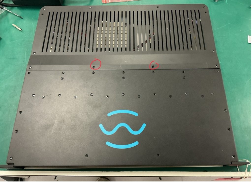
Step 1. Ensure the unit is powered off. Step 2. Unscrew both Lids. Note that 9 of the lid screws are for the heatsinks and should not be touched. Also note that 2 of the screws are shorter (4mm) these should be reserved for the back lid. Place all screws in a small cup.
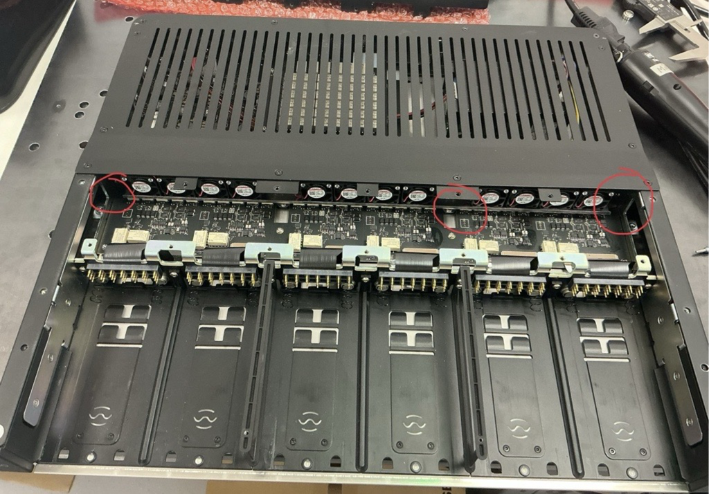
Step 3. Inside the metalwork are some loose metal spacers called shims. These are bespoke heights and should not be disturbed. Place tape along the gap of the side arm, ensuring that no shims fall out. Then, balance the unit on it’s side.
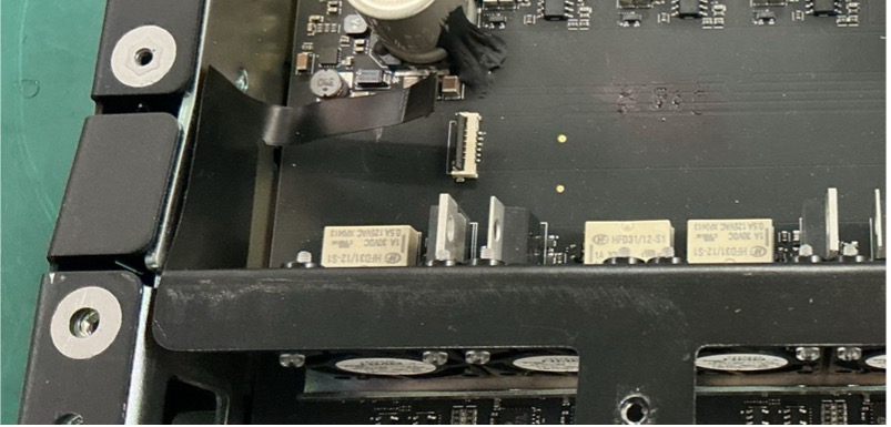
Step 4. Remove the two silver hex screws in the centre of the base plate, and place the unit flat on the bench.
Step 5. Open the latch on the fan FFC connector and gently pull out the ribbon cable. Tweezers may be needed.
Step 6. The two side flaps of the flex PCB are glued to the chassis. Carefully peel them away from the chassis. Use a spudger if necessary.
Step 7. Gently wiggle and lift the fan assembly out of the chassis.
Installing New Fan
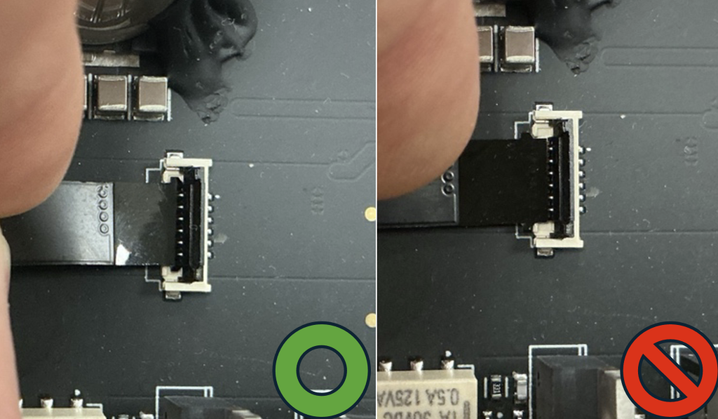
Step 1. Place the new fan assembly into position. Step 2. Connect the FFC ribbon cable. Ensure that both ears of the FFC ribbon are latched inside the connector.
Step 3. (Optional) Check continuity using a multimeter to confirm no shorts. Step 4. Ensuring that no shims fall out, balance the unit on it’s side. (tape can be used to prevent any shims from falling out of the side arms). Step 5. Install the two silver screws into the base plate. Lay the unit flat.
Testing and Reassembly
Step 1. Power on the unit to test the fans. Wait until you hear 6 relay clicks to indicate the unit has booted up. Step 2. Using a hot air gun, blow air on to the temperature sensors and see if the fan blades spin on each bank. Depending on air temperature it should take up to 5 seconds to start spinning. If the fans do not spin, check the FFC connector is seated correctly.
Step 3. Power off the unit. Step 4. Remove the side arm tape and reinstall all lid screws. Ensure the two 4 mm short screws are returned to the correct holes on the back lid.
Privacy & Cookies
We respect your privacy. We only collect and use your IP address for currency conversion when using our Shopify integration. This helps us provide the right currency based on your location. We don’t share this data and only keep it for as long as necessary. For our full statement Click Here